
Rectifier Chargers GR (B)
The GR(B)-series is the basic charger available in the TECNED GR product family with limited options. It strictly adheres to a truly industrial design with convection cooling and is built for 20 years operational life-time.
The TECNED GR (B) Rectifier / Charger series is available from 24Vdc to 650Vdc nominal with up to 100A output in a single enclosure.
TECNED rectifier/chargers are based on Thyristor + Concept (SCR+IGBT) technology with a galvanic separation transformer, input PF 0.98, low input harmonics (<10%), standard low DC ripple (< 2% for 3-phase systems).
Like all GR-models, the GR(B)-series is short circuit proof, includes high DC protection as standard to protect the load and delivers a steady output voltage under al operating conditions.
Optional built-in batteries up to 9x 12V/100Ah for 110Vdc installations can provide back-up for small and medium installations. In combination with 12V/40AH and 12V/75AH batteries, up to 8 x 2P distributions MCB’s can be fitted for easy implementation.
The GR(B)-series is supplied in a floor standing sheet steel cabinet with bottom cable entry.
Tecned GR(B) Specifications
| 1- INPUT | ||
| Input voltage single phase | 110 / 120 / 200 / 220 / 230 / 240 / 277V, (2W+E) | |
| Input voltage three phase | 208 / 220 / 240 / 380 / 400 / 415 / 480V, (3W+E) | |
| Input voltage range | 15%/-20% (20% start battery operation) | |
| nominal input frequency | [Hz] | 50/60 |
| allowable frequency range | [Hz] | 40-70 |
| input current THD | [%] | <10 |
| power factor | PF | 0.98 |
| overall efficiency | [%] | Up to 95% (depending on DC bus voltage) |
| galvanic isolation | Yes (input isolation transformer) | |
| 2- OUTPUT | ||
| nominal output voltage | [Vdc] | 24, 48, 60, 110 (125), 380 Vdc |
| Battery charging characteristic | IU (DIN 41773), T° compensated floating voltage | |
| DC voltage range | [Vdc] | 24 – 280Vdc |
| Float charge setting (Cell) | [Vdc] | 1.40-1.42V for Ni-cd or 2.17 -2.27V for Lead acid |
| output current I-nominal | [A] | 1A to 100A (depending on DC voltage level) |
| battery charge current setting | [%] | 0.1C to max-current adjustable with dip-switch |
| output voltage regulation | [%] | < 1 ( 0.5% static) |
| load step response time | [ms] | < 200 (0-to 100%) |
| ripple voltage (without battery) | [%] | < 5% with 1Ph input / < 2% with 3Phase input |
| current limiting | [%] | Yes |
| current accuracy | [%] | 2% |
| long-term stability | [%] | 0.15% for 1000 Hrs |
| 3 – PROTECTION | ||
| soft start inrush current limit | ||
| input | (AC) | short circuit protection by MCB |
| input | (AC) | overload protection electronically limited |
| output | (DC) | short circuit protection by Fuse / MCB |
| output | (DC) | overvoltage alarm (DC high) / auto-off / manual reset |
| battery overload/short circuit protection by Fuse / MCB and battery low voltage alarm | ||
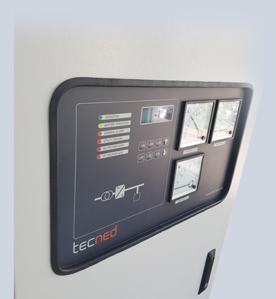
| 4 – ANALOGE METERING | ||
|
|
||
| 5 – BASIC USER INTERFACE | ||
|
|
||
| 6 – EXTERNAL CONTACT | ||
| general alarm : 1 potential free contacts rated max 250VAC or 30VDC / 2A | ||
| 7 – DC DISTRIBUTION | ||
|
|
||
| 8 – ENCLOSURE | ||
|
finish : powder coating RAL 7035 battery : internal battery space for units up to 20A battery capacity : Up to 9 blocks 12V/100AH internal dims (hxwxd) (mm) : 1500 x 600 x 450mm weight : 70-220kG depending on configuration (excl. battery) enclosure : sheet steel cabinet with front door access cable entry : from bottom protection : IP 20 Acc IEC 60529 |
||
| 9 – STANDARDS | ||
|
ISO9001 : Quality management systems
IEC-60146 : Semiconductor converters – General requirements and line commutated converters EMC 55011 : Industrial, scientific, and medical (ISM) radio-frequency equipment—Radio disturbance characteristics—Limits and methods of measurement; Amendment A1:1999 to EN 55011:1998. IEC- 62040-1 : Uninterruptible power systems (UPS) Part 1: General and safety requirements for UPS IEC 61000-3-12 : Electromagnetic compatibility (EMC) – Part 3-12: Limits – Limits for harmonic currents produced by equipment connected to public low-voltage systems with input current >16 A and L 75 A IEC/61000-6-5 : Low voltage AC Surge 1.2/50 µs, 2 kV line to ground,1 kV line to line (equipment installed in power stations and MV substations. Low voltage DC Surge 1.2/50 µs, 2 kV line to ground, 1 kV line to line |
||
| 10 – ENVIRONMENT | ||
|
storage temperature : -25 to + 70 °C operating temperature : -10 to + 40 °C humidity : max. 95% installation altitude : < 1000 meter at full rate derating : 7% per 1000 meter to 4000m audible noise : 45 dBA cooling : natural cooling (convection cooling) |
||
| 11 – TECHNOLOGY | ||
|
|
||
Copyright 2024 @ Tecned.com
Tjalke de Boerstrjitte 12
8561 EL, Balk
The Netherlands
+31-514-820222
Enquiries: sales@tecned.com