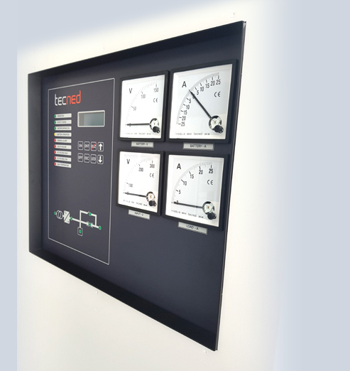
Rectifier Chargers GR (D)
Battery-backed DC-power supply systems are securing the supply power to monitoring and regulation devices for oil & gas installations, industrial processes, public transportation and power grid. DC back-up units are widely used in nearly all fields of industry and public life and play a vital role in areas of safety, power management and power availability.
The TECNED GR (D) Rectifier / Charger series is available from 24Vdc to 650Vdc nominal with up to 600A output in a single enclosure. The GR (D) series can be configured to charge common battery types from VRLA to NICAD and to include boost-charge and equalize options.
TECNED rectifier/chargers are based on Thyristor + Concept (SCR+IGBT) technology with a galvanic separation transformer, input PF 0.98, low input harmonics (<10%), standard low DC ripple (< 2% for 3-phase systems).
The GR (D) series can be supplied as standard or fault tolerant systems within a single enclosure to meet customer requirements for safety and reliability.
The GR-D model includes an additional digital controller with LCD display that shows the systems current state of operation and system values, allows setting of system parameters and includes event and alarm logs.

Tecned GR(D) Specifications
| 1- INPUT | ||
| Input voltage single phase | 110 / 120 / 200 / 220 / 230 / 240 / 277V, (2W+E) | |
| Input voltage three phase | 208 / 220 / 240 / 380 / 400 / 415 / 480V, (3W+E) | |
| Input voltage range | 15%/-20% (20% start battery operation | |
| nominal input frequency | [Hz] | 50/60 |
| allowable frequency range | [Hz] | 40-70 |
| input current THD | [%] | <10 |
| power factor | PF | 0.98 |
| overall efficiency | [%] | Up to 95% (depending on DC bus voltage) |
| galvanic isolation | Yes (input isolation transformer) | |
| 2- OUTPUT | ||
| nominal output voltage | [Vdc] | 24, 48, 60, 110 (125), 220 (240), 380 Vdc |
| Battery charging characteristic | IU (DIN 41773), T° compensated Battery charging characteristic floating voltage | |
| DC voltage range | [Vdc] | 24 – 380Vdc |
| Float charge setting (Cell) | [Vdc] | 1.40-1.42V for Ni-cd or 2.17 -2.27V for Lead acid |
| output current I-nominal | [A] | 10A to 600A (depending on DC voltage level) |
| battery charge current setting | [%] | 0.1C to max current |
| output voltage regulation | [%] | < 1 ( 0.5% static) |
| load step response time | [ms] | < 200 (0-to 100%) |
| ripple voltage (without battery) | [%] | <5% with 1Ph input / < 2% with 3Phase input |
| current limiting | [%] | Yes |
| current accuracy | [%] | 2% |
| long-term stability | [%] | 0.15% for 1000 Hrs |
| 3 – PROTECTION | ||
| soft start inrush current limit | ||
| input | (AC) | short circuit protection by MCB |
| input | (AC) | overload protection electronically limited |
| output | (DC) | short circuit protection by Fuse/ MCB |
| output | (DC) | overvoltage alarm (DC high) / auto-off / manual reset |
| battery overload/short circuit protection by Fuse/ MCB and battery low voltage alarm | ||
| 4 – BASIC USER INTERFACE | ||
|
|
||
| 5 - EXTERNAL CONTACT (max 250VAC or 30VDC / 2A) | ||
| Potential free contacts: general alarm / Utility failure / DC low / DC high | ||
| 6 - ENCLOSURE | ||
| Type | : Floor standing cabinet with front door acccess / Aluzinc frame | |
| Finish | : Powder coat RAL 7035 | |
| Dimensions | : From 1800 x 600 x 600 to 2000 x 800 x 800 mm per assembly (depending on rating) | |
| Weight | : Up to 650 Kg per assembly (depending on rating) | |
| Protection | : standard IP 20 (Option up to IP 65) | |
| 7 – STANDARDS | ||
| ISO9001 | : Quality management systems | |
| IEC- 60146 | : Semiconductor converters – General requirements and line commutated converters | |
| EMC 55011 | : Industrial, scientific, and medical (ISM) radio-frequency equipment—Radio disturbance characteristics—Limits and methods of measurement; Amendment A1:1999 to EN55011:1998. | |
| IEC- 62040-1 | : Uninterruptible power systems (UPS) Part 1: General and safety requirements for UPS | |
| IEC 61000-3-12 | : Electromagnetic compatibility (EMC) – Part 3-12: Limits -Limits for harmonic currents produced by equipment connected to public low-voltage systems with input current>16 A and ≤ 75 A | |
| IEC/61000-6-5 | : Low voltage AC Surge 1.2/50 μs, 2 kV line to ground,1 kV line to line (equipment installed in power stations and MV substations. Low voltage DC Surge 1.2/50 μs, 2 kV line to ground, 1 kV line to line | |
| 8 – ENVIRONMENT | ||
| storage temperature | : -25 to + 70 °C | |
| operating temperature | : -10 to + 40 °C | |
| humidity | : max. 95% | |
| installation altitude | : < 1000 meter at full rate | |
| derating | : 7% per 1000 meter to 4000m | |
| audible noise | : 50 to 65 dBA (depending on cooling) | |
| 9 – TECHNOLOGY | ||
|
|
||
Copyright 2024 @ Tecned.com
Tjalke de Boerstrjitte 12
8561 EL, Balk
The Netherlands
+31-514-820222
Enquiries: sales@tecned.com
